-

Adversary Simulation
Our best in class red team can deliver a holistic cyber attack simulation to provide a true evaluation of your organisation’s cyber resilience.
-

Application
SecurityLeverage the team behind the industry-leading Web Application and Mobile Hacker’s Handbook series.
-

Penetration
TestingMDSec’s penetration testing team is trusted by companies from the world’s leading technology firms to global financial institutions.
-

Response
Our certified team work with customers at all stages of the Incident Response lifecycle through our range of proactive and reactive services.
ARM64 stack internals and obfuscation on Apple Silicon
Introduction
We closely monitor the detection mechanisms employed by EDR sensors to better understand how they identify suspicious activity. Recently, we observed that one of the major players in the EDR market takes an interesting approach to walking thread call stacks: rather than implementing a custom unwinder, it uses the built-in macOS diagnostic utility spindump.
The presence of /usr/sbin/spindump caught our attention and prompted a deeper investigation into how the sensor collects and analyses call stacks. Although macOS EDR sensors are generally less aggressive than their Windows counterparts, this discovery led me to explore whether call-stack obfuscation—a well-established technique on Windows—could be adapted for ARM64 macOS. That work, and its implications for EDR visibility, is the focus of this post.
The ARM64 stack model
Before unwind metadata makes sense, three registers need distinct jobs: sp tracks the current allocation boundary, x29 anchors a stable frame record, and x30 carries the immediate return address.
| Register | Role | Unwinding significance |
|---|---|---|
sp | Current stack pointer; moves as storage is allocated and released. | The caller’s value is reconstructed by the unwind recipe. |
x29\FP | Conventional frame pointer in a framed function. | Points at the frame’s saved FP/LR record. |
x30\LR | Link register containing the return address. | Saved in memory by non-leaf framed functions; may remain live in a leaf function. |
x19–x28 | Callee-saved general-purpose registers. | Recovered only when the recipe says that a function saved them. |
ARM64 branch instructions
Unlike x86_64 architecture where we can use the call instruction to invoke a function, there is no such instruction in Arm64 ISA. Under the hood, a call instruction pushes the return address on to stack and updates the instruction pointer thus transfering control to a new code block. A subsequent ret instruction pops the return address off the stack, places it in eip/rip and execution is resumed. But the story is different in the land of Arm64, control flow instructions that implement a function call come under the branch and link category. This is because Arm64 has a dedicated Link Register/LR which is x30 to store the return address. Because of this, function invocation branching instructions mainly fall into two camps – one that modifies x30 and the other that preserves it. Each instruction in their respective camps will have a PAC version, we will discuss about PAC in detail in coming sections.
Instructions that write x30
| Instruction | Meaning | Effect on x30 |
|---|---|---|
bl label | Direct call | x30 = address of next instruction |
blr xn | Indirect call through xn | Same |
blraa xn, xm | Authenticated indirect call, key A | Same |
blraaz xn | Authenticated indirect call, key A, zero modifier | Same |
blrab xn, xm | Authenticated indirect call, key B | Same |
blrabz xn | Authenticated indirect call, key B, zero modifier | Same |
A non-leaf function, ie a function that calls other functions need to explicitly store the x30 value on to the stack before branching to a target function block. This is trivial because branch with link instructions update x30 before the transfer, if we don’t preserve the return address somewhere there is no way to transfer the control back to caller when callee returns. This is the reason why the return address PC is stored at a known stack offset 0x8, relative to the frame pointer in the callee’s frame ( [x29 + 0x8] ).
Function transfers that preserve x30
These are commonly used for tail calls and linker stubs:
| Instruction | Meaning |
|---|---|
b label | Direct branch/tail call |
br xn | Indirect branch/tail call |
braa xn, xm | Authenticated indirect branch, key A |
braaz xn | Authenticated indirect branch, key A, zero modifier |
brab xn, xm | Authenticated indirect branch, key B |
brabz xn | Authenticated indirect branch, key B, zero modifier |
Keep in mind instructions that help function transfers that preserve x30 play a major role in crafting synthetic frames.
A conventional prologue and epilogue
ARM64 has no dedicated push or pop. It commonly combines stack adjustment with paired store (stp) and load (ldp) instructions as shown below:
_function:
    stp     x29, x30, [sp, #-16]!   // subtract 16, then save FP/LR
    mov     x29, sp                 // establish a stable frame pointer

    // function body

    ldp     x29, x30, [sp], #16     // restore FP/LR, then add 16
    ret                              // branch to restored x30
These two instructions form a 16-byte push/pop pair. Remember:
- Each
xregister is 8 bytes - The stack grows toward lower addresses
x30contains the return address
Lets work out an example to solidy the undersanding of how paired store and load instructions are used to emulate push/pop mechanism. Assume initially:
sp  = 0x1000
x29 = caller's frame pointer
x30 = return address
Store pair : push
stp x29, x30, [sp, #-16]!
The ! means update sp before accessing memory, this is called a pre-index stack adjustment. Here x29 and x30 act as source registers to store the callers frame pointer and return address respectively on stack at memory[sp + 0] and memory[sp + 8]
sp = sp - 16;
memory[sp + 0] = x29;
memory[sp + 8] = x30;
So afterward:
              higher addresses

0x1000        old SP
0x0FF8        saved x30      // return address
0x0FF0        saved x29      // previous frame pointer
              ^
              sp

              lower addresses
The instruction combines stack allocation and two stores [sp + 0] and [sp + 8].
Load pair: pop
Lets look at how pop is emulated using paired load instruction. This is a post-indexing stack adjustment where sp is accessed first, after loading x29 and x30 the sp gets incremented by 16 bytes
ldp x29, x30, [sp], #16
The break down of the ldp operation on sp is shown below.
x29 = memory[sp + 0];
x30 = memory[sp + 8];
sp = sp + 16;

//afterward
sp  = 0x1000
x29 = restored caller frame pointer
x30 = restored return address
Therefore combining these two operations we have proper mechanism to restore caller’s state when callee executes a return instruction.
stp x29, x30, [sp, #-16]!   // push x29 and x30
...
ldp x29, x30, [sp], #16     // pop x29 and x30
ret                          // jump to restored x30
A complete minimal frame commonly looks like:
stp x29, x30, [sp, #-16]!   // save caller FP and return address
mov x29, sp                  // establish this function's FP

// function body and beyond this point the callee can go ahead and modify sp

ldp x29, x30, [sp], #16     // restore caller FP and return address
ret
The rough x86-64 analogy is push during the prologue and pop during the epilogue. The notable difference is that x86-64 call pushes the return address automatically, while ARM64 bl places it in x30, so the callee explicitly saves x30 when needed.
Canonical Frame Address : the caller boundary
On ARM64 framed functions, it generally represents the caller’s SP immediately before the current function was entered. We discussed how callee establish its frame by saving caller’s frame ([x29])and return address ([x30]) on the stack before it extends its frame for its locals and callee saved registers.
stp x29, x30, [sp, #-16]! // 16 bytes push operation - saving caller's frame and return address
mov x29, sp               // establishing callee's frame
The relationship between sp and CFA is shown below. This is nothing but caller’s SP immediately before the current function was entered which is value in sp before stp x29, x30, [sp, #-16]! was executed, because the frame record consumed 16 bytes.
CFA = x29 + 16
After a frame is established, a function may continue moving sp to reserve locals and temporary storage while x29 remains stable:
Entry:      SP = 0x1010
Frame:     SP = 0x1000, x29 = 0x1000
Locals:    SP = 0x0F80, x29 = 0x1000

CFA = x29 + 16 = 0x1010
Now we can easily access return address, callers frame and preserved register relative to x29 or CFA. This is demonstrated below. This is similar to esp/ebp relative access in x86 architecture.
//general conversion rule

x29 + N = CFA + (N - 16)

//accessing data on stack relative to x29

x29 + 16   CFA / caller's SP
x29 +  8   saved x30 / caller PC
x29 +  0   saved x29 / caller FP
x29 -  8   saved x19
x29 - 16   saved x20
x29 - 24   saved x21
x29 - 32   saved x22
x29 - 40   saved x23
x29 - 48   saved x24
x29 - 56   saved x25
x29 - 64   saved x26
x29 - 72   saved x27
x29 - 80   saved x28

//accessing data on stack relative to CFA (x29 + 0x10)

CFA +  0   caller's SP
CFA -  8   saved x30 / caller PC
CFA - 16   saved x29 / caller FP
CFA - 24   saved x19
CFA - 32   saved x20
CFA - 40   saved x21
CFA - 48   saved x22
CFA - 56   saved x23
CFA - 64   saved x24
CFA - 72   saved x25
CFA - 80   saved x26
CFA - 88   saved x27
CFA - 96   saved x28
Frame record
Now the time has come to discuss about most important subject which is the shape of a function frame. The x29 register normally forms a linked list of stack-frame records. Each frame will have a shape as shown below.
Higher addresses

x29 + 0x10   caller's original SP / CFA
x29 + 0x08   saved x30 / return address
x29 + 0x00   saved caller x29            // current x29
             locals and saved registries
sp           current stack allocation boundary

Lower addresses
Since frames are linked using x29 we dont need to know size of each frame during the unwinding. Using pointer chain stored in the register x29 is enough to fetch frame pointers of previous callers (x29) and their return address or PC ( x29 + 0x08 ). Nevertheless this is mainly dependent on unwind recipie selected for a specific return address or PC placed on the stack. We will discuss recipies in detail in following sections. For now bear in mind for any non-leaf function, ie a function that calls another function, each frame needs to be placed in the x29 pointer chain.
Lets discuss a scenario where we have five functions a, b, c, d and e. The direction of invocation is as follows a->b->c->d->e where each frame is denoted as Fx; x is name of the function. By using [x29] we can easily walk the whole chain as show below.
current x29 = Fe
      │ [Fe]
      ▼
     Fd ──► Fc ──► Fb ──► Fa

[Fe + 8] = return location in d
[Fd + 8] = return location in c
[Fc + 8] = return location in b
[Fb + 8] = return location in a
This chain is valuable but not sufficient for every function. Leaf functions may omit a frame, tail calls may remove a logical transition, and unusual assembly or transition frames require formal unwind metadata.
Where unwind information lives in Mach-O
The stack layout cannot be treated as a single source of the truth during the unwind process. because the stack does not inherently contain a “frame mode” tag. The current program counter acts as a key into metadata stored in the Mach-O image. This key piece of information acts as a signpost for the unwinder, indicating how to interpret the stack layout. The major items that help in this process are :
x29register- stack pointer
sp - return address
PC - unwinder recovers non-volatalile registers (callee saved) during exception handling.
__TEXT,__unwind_info
We are familiar with the parsing of RUNTIME_FUNCTION structures in .pdata section in a PE file. In essence that is exactly what we are trying to acheive here. Only difference is how unwind data is stored in Macho file. The unwind related metadata are stored in __TEXT,__unwind_info . The __TEXT,__unwind_info section begins with an unwind_info_section_header
#define UNWIND_SECTION_VERSION 1

struct unwind_info_section_header {
    uint32_t version;
    uint32_t commonEncodingsArraySectionOffset;
    uint32_t commonEncodingsArrayCount;
    uint32_t personalityArraySectionOffset;
    uint32_t personalityArrayCount;
    uint32_t indexSectionOffset;
    uint32_t indexCount;
};
The header tells you where the array of unwind_info_section_header_index_entry records is located and how many entries it contains. All section offsets above are byte offsets from the beginning of __unwind_info. On Apple Silicon Mach-O, integer fields are little-endian. Immediately named arrays contain 32-bit encodings or 32-bit personality deltas.
struct unwind_info_section_header_index_entry {
    uint32_t functionOffset;
    uint32_t secondLevelPagesSectionOffset;
    uint32_t lsdaIndexArraySectionOffset;
};

// used when UNWIND_SECOND_LEVEL_COMPRESSED
struct unwind_info_section_header_lsda_index_entry {
    uint32_t functionOffset;
    uint32_t lsdaOffset;
};
The unwind_info_section_header_index_entry points to a second-level page. If that page’s kind is UNWIND_SECOND_LEVEL_REGULAR, it contains a regular page header followed by regular entries.
#define UNWIND_SECOND_LEVEL_REGULAR 2

enum unwind_second_level_page_kind {
    UNWIND_SECOND_LEVEL_REGULAR    = 2,
    UNWIND_SECOND_LEVEL_COMPRESSED = 3
};

struct unwind_info_regular_second_level_page_header {
    uint32_t kind;
    uint16_t entryPageOffset;
    uint16_t entryCount;
};


struct unwind_info_regular_second_level_entry {
    uint32_t functionOffset;   // image-relative
    uint32_t encoding;
};
Below is a simple C style pseudocode to parse unwind code by parsing structs mentioned above. This code parses unwind code stored as UNWIND_SECOND_LEVEL_REGULAR. The UNWIND_SECOND_LEVEL_COMPRESSED needs different parsing.
Optional<uint32_t>
FindRegularUnwindEncoding(
    const uint8_t *unwindSection,
    size_t unwindSectionSize,
    uintptr_t runtimeImageBase,
    uintptr_t targetAddress)
{

  /*
   *
   * All offsets inside these structures are relative to their documented base.
   * Header 						--> unwind_info_section_header
	 * IndexEntry 				--> unwind_info_section_header_index_entry
	 * RegularPageHeader  --> unwind_info_regular_second_level_page_header
	 * RegularEntry 			--> unwind_info_regular_second_level_entry
   *
   *
  */

  /*
   * functionAddress = imageBase + entry.functionOffset;
	 * page     = unwindInfoBase + index.secondLevelPagesSectionOffset;
	 * entries  = pageAddress + page.entryPageOffset;
   *
  */
    if (targetAddress < runtimeImageBase)
        return NONE;

    uint64_t target64 = targetAddress - runtimeImageBase;
    if (target64 > UINT32_MAX)
        return NONE;

    uint32_t targetOffset = (uint32_t)target64;

    // 1. Read and validate the top-level unwind_info_section_header
    Header *header = CheckedRead(
        unwindSection,
        unwindSectionSize,
        offset = 0,
        size = sizeof(Header));

    if (header == NULL || header->version != 1)
        return NONE;

    if (header->indexCount < 2)
        return NONE;  // Normally includes a final sentinel entry.

    IndexEntry *index = CheckedArray(
        unwindSection,
        unwindSectionSize,
        header->indexSectionOffset,
        header->indexCount,
        sizeof(IndexEntry));

    if (index == NULL)
        return NONE;

    /*
     * 2. Find first-level entry i satisfying:
     *
     *    index[i].functionOffset <= targetOffset
     *        < index[i + 1].functionOffset
     *
     * The final index entry acts as the end sentinel.
     */
    int i = UpperBoundByFunctionOffset(
                index,
                header->indexCount,
                targetOffset) - 1;

    if (i < 0 || i + 1 >= header->indexCount)
        return NONE;

    uint32_t rangeStart = index[i].functionOffset;
    uint32_t rangeEnd   = index[i + 1].functionOffset;

    if (targetOffset < rangeStart || targetOffset >= rangeEnd)
        return NONE;

    uint32_t pageSectionOffset =
        index[i].secondLevelPagesSectionOffset;

    if (pageSectionOffset == 0)
        return NONE;

    // 3. Read the second-level page header.
    RegularPageHeader *page = CheckedRead(
        unwindSection,
        unwindSectionSize,
        pageSectionOffset,
        sizeof(RegularPageHeader));

    if (page == NULL)
        return NONE;

    if (page->kind != UNWIND_SECOND_LEVEL_REGULAR) {
        // A compressed second-level page requires different parsing.
        return NONE;
    }

    /*
     * entryPageOffset is relative to the beginning of this
     * second-level page, not the beginning of __unwind_info.
     */
    uint64_t entriesOffset =
        (uint64_t)pageSectionOffset + page->entryPageOffset;

    RegularEntry *entries = CheckedArray(
        unwindSection,
        unwindSectionSize,
        entriesOffset,
        page->entryCount,
        sizeof(RegularEntry));

    if (entries == NULL || page->entryCount == 0)
        return NONE;

    /*
     * 4. Find the closest function entry whose starting offset is
     *    less than or equal to targetOffset.
     */
    int e = UpperBoundByFunctionOffset(
                entries,
                page->entryCount,
                targetOffset) - 1;

    if (e < 0)
        return NONE;

    uint32_t functionStart = entries[e].functionOffset;

    // Determine the end of this function's encoding range.
    uint32_t functionEnd;

    if (e + 1 < page->entryCount)
        functionEnd = entries[e + 1].functionOffset;
    else
        functionEnd = rangeEnd;

    if (targetOffset < functionStart ||
        targetOffset >= functionEnd)
        return NONE;

    // 5. This is the compact-unwind encoding covering targetAddress.
    return entries[e].encoding;
}
__eh_frame
Stores DWARF Frame Description Entries and call-frame instructions for layouts that compact unwind cannot represent. The DWARF unwinding is byond the scope of this blog and wont be discussed further.
Decoding ARM64 compact-unwind recipes
The lookup begins with an address, not a symbol name and not a scan of the function’s prologue:
- Normalize PC — remove or normalize ARM64e PAC information, we will discuss about PAC later. Ignore this step if build is Arm64.
- Find the containing Mach-O image — identify the loaded
__TEXTrange. - *Convert to an image-relative offset — account for the loaded image base and ASLR.
- Search the first-level index — select the page covering the function offset.
- Search the regular or compressed second-level page — locate the precise function range.
- Read and decode the compact encoding — select the frame, frameless, DWARF or no-unwind recipe.
functionOffset = normalizedPC − loadedImageBase
When the PC was recovered from a saved return address, lookup may use PC−1. A return address points immediately after a calling instruction; subtracting one byte keeps lookup inside the call-site function’s range. It changes recipe selection, not stack offsets. The PC does not carry the recipe. Two stack records with identical bytes can unwind differently if their PCs select different Mach-O entries.
The high mode bits select the broad strategy:
mode = encoding & 0x0F000000
| Mode | Encoding | Caller recovery |
|---|---|---|
| None | 0x00000000 | No official compact recipe; stop or use a separate fallback. |
| Frameless | 0x02000000 | Use the current SP, encoded stack size and live LR (x30). |
| DWARF | 0x03000000 | Use the referenced FDE and its CFI instructions from __eh_frame. |
| Frame | 0x04000000 | Use the conventional x29 frame record. |
Frame mode
Compiler sets the mode of any non leaf function to frame mode. The fundamental frame-mode recipe is:
callerFP = *(uint64_t *)(x29 + 0)
callerPC = *(uint64_t *)(x29 + 8)
callerSP = x29 + 16 // Canonical frame address/cfa
Decoding 0x04000001 and 0x0400001F
Low bits advertise saved register pairs. For example:
0x04000001 = 0x04000000 FRAME
           | 0x00000001 X19/X20_PAIR
The resulting layout is:
[x29 - 0x10] = saved x20
[x29 - 0x08] = saved x19
[x29 + 0x00] = caller x29
[x29 + 0x08] = saved return PC
 x29 + 0x10  = caller SP / CFA
The mode 0x0400001F is still frame mode, while all five integer-register pair bits are present:
0x0400001F & 0x0F000000 = 0x04000000  // FRAME
0x0400001F & 0x0000001F = 0x0000001F  // all GPR pairs
| Pair bit | Registers | Frame-relative storage |
|---|---|---|
0x01 | x19, x20 | x19=[FP−8], x20=[FP−16] |
0x02 | x21, x22 | x21=[FP−24], x22=[FP−32] |
0x04 | x23, x24 | x23=[FP−40], x24=[FP−48] |
0x08 | x25, x26 | x25=[FP−56], x26=[FP−64] |
0x10 | x27, x28 | x27=[FP−72], x28=[FP−80] |
These saves are not required merely to find the next PC. They matter when an unwinder reconstructs truthful nonvolatile register state for debugging or exception processing.
Frameless mode
A frameless function has no conventional [x29,x30] record. The encoded stack size restores the caller’s SP, and the live link register supplies the immediate caller PC:
stackSize = ((encoding & 0x00FFF000) >> 12) * 16

callerSP = currentSP + stackSize
callerPC = live x30
callerFP = current x29
This commonly describes a small leaf function that does not execute bl/blr, allowing x30 to remain untouched. These instructions are discussed in detaail in following sections.
DWARF mode
The low 24 bits identify a Frame Description Entry:
fdeOffset  = encoding & 0x00FFFFFF
fdeAddress = __eh_frame_start + fdeOffset
The unwinder executes that entry’s call-frame instructions. The rules may use x29, sp, or changing CFA definitions; there are no universal fixed offsets. This is beyond the scope of this post.
How an unwinder reconstructs a call stack
Unwinding is a repeated state transformation. Each PC selects a recipe; that recipe produces a virtual caller state; the recovered caller PC selects the next recipe.
state = { PC, SP, x29, x30, nonvolatile registers }

repeat:
    recipe = lookup(state.PC)
    caller = apply(recipe, state, stack memory)
    emit caller.PC
    state = caller
A frame-mode walking
For 0x04000001, the operation is:
caller.x20 = [FP - 16]
caller.x19 = [FP - 8]
caller.x29 = [FP + 0]
caller.PC  = [FP + 8]
caller.SP  = FP + 16
The recovered x19/x20 values make the virtual caller state accurate, but [FP] and [FP+8] are what link traversal to the next frame.
Mixed-mode walking
A call chain can have frames with different modes, an unwinder performs unwind recipie decoding at each step of frame walking to find out appropriate unwinding strategy. A very high level overview of the mixed mode unwinding is shown below
(pc, sp, fp=x29, lr=x30)
        │
        V
look up current PC in __unwind_info
        │
        ├─ FRAME     -> read [fp], [fp+8], set sp=fp+16
        ├─ FRAMELESS -> use live lr, add encoded stack size
        └─ DWARF     -> execute FDE/CFI rules
        │
        V
repeat using recovered caller PC
An unwinder reads specific locations prescribed by metadata. It does not normally scan arbitrary stack words looking for address-like values.
Reasons to stop
- The recipe is
NO_UNWINDor mode zero with no fallback. - Required memory is unreadable.
- The next frame pointer is invalid, misaligned, or does not progress toward the caller.
- The recovered PC does not map to valid executable or unwind information.
- An ARM64e saved return address cannot be normalized or authenticated correctly.
The unwinder generally cannot tell whether a matching record came from a real prologue or was synthesized. If the PC selects a valid recipe and memory matches that recipe, it can be traversed as a legitimate frame.
ARM64e pointer authentication primer
Pointer Authentication Codes do not encrypt an address, they attach a short, keyed integrity value to a pointer. A later control transfer can authenticate that value before trusting the pointer. The address is still present; its spare high bits carry the signature. Thus PAC signs and autheticates a raw pointer before using it. This process is very crucial in control transfers like indirect calls and when the function returns, respective pointers are validated before allowing the transfer of the control. The pointers are classified into mainly two groups :
- Instruction pointers
- Data pointers
ARM64e provides seperate key classes to protect code/instruction pointers and data pointers. The Instruction Key A (IA) and Instruction Key B (IB) are used to sign instruction/code pointers. The Data Key A and Data Key B are used to data pointers
The secret key material is hardware-managed; these short names select a key rather than exposing its value.
| Keys | Description |
|---|---|
| Instruction key A | Commonly used by the ARM64e ABI for callable function pointers and authenticated indirect branches. |
| Instruction key B | Used by the ARM64e return-address convention. In this project, every synthetic saved LR is signed with IB. |
| Data key A | Signs data pointers under schemas that select the A data key. It is separate from executable-pointer authentication. |
| Data key B | The second data-pointer key selection. A pointer signed with one key does not authenticate under another. |
A very high level view of signing process is shown below. Arm64e provides wide variety of signing and authentication instructions, signing instructions are used to sign a raw pointer and when the system wants to authenticate the pointer there are instructions to prove the validity of the same pointer in a given context called discriminator or modifier. This is a very important concept to understand PAC signing, discriminator provides a context to signing, Arm64e platform provides a broad instruction set to the user based on the kind of context required for the sigining.
signed = PAC(raw_pointer, key, discriminator) -> AUT(signed_pointer, same key, same discriminator) = raw
A discriminator is a non-secret context value mixed into the PAC calculation alongside the pointer and secret key. Arm instructions also call this input a modifier. It answers: “In which context should this signed pointer be valid?” The exact same discriminator must be supplied when the pointer is authenticated. At the lowest level a discriminator is an arbitrary 64-bit value. The diversity of signing instruciton is mainly dictated by the discriminator, a rough classification shown below.
- register-discriminator form
- zero-discriminator form
- SP return-address form
- zero return-address form
- fixed x17/x16 form
PAC Signing
Register-discriminator form
This is a two register form where xd can be any register that contains raw pointer that needs signing, xn is the discriminator/modifier value in a register or it can be value in stack pointer.
pacia  xd, xn      // instruction pointer signed using key A
pacib  xd, xn      // instruction pointer signed using key B
pacda  xd, xn      // data pointer signed using key A
pacdb  xd, xn      // data pointer signed using key B
zero-discriminator form
This is a single register form where modifier is value 0 and xd is the register that hold the raw pointer the needs signing.
paciza xd          // instruction pointer signed using key A
pacizb xd          // instruction pointer signed using key B
pacdza xd          // data pointer signed using A
pacdzb xd          // data pointer signed using B
SP return-address form
The return addresses in x30 can be signed with value in sp chosen as the discriminator value.
paciasp            // x30 = sign(x30, IA, sp)
pacibsp            // x30 = sign(x30, IB, sp)
Zero return-address form
This form is idenical to SP return-address form but here discrimator/modifier value is 0
paciaz             // x30 = sign(x30, IA, 0)
pacibz             // x30 = sign(x30, IB, 0)
Fixed x17/x16 form
In the foxed form raw pointer is read from x17 and modifier is stored in x16
pacia1716           // x17 = sign(x17, IA, x16)
pacib1716           // x17 = sign(x17, IB, x16)
This is not an exhaustive list of instructions, such discussion is beyond the scope of this blog. You can refer Arm64 manual to learn more about the instrucion set.
PAC Authentication
The classic ARMv8.3/arm64e set has 14 standalone authentication instructions, matching the signing forms discussed above.
// uses key A
autia      xd, xn     // arbitrary pointer and discriminator
autiza     xd         // arbitrary pointer, zero discriminator
autia1716             // x17 pointer, x16 discriminator
autiasp                // x30 pointer, SP discriminator
autiaz                 // x30 pointer, zero discriminator

// uses key B
autib      xd, xn
autizb     xd
autib1716
autibsp
autibz

//Data pointer auth
autda      xd, xn     // data key A
autdza     xd         // data key A, zero discriminator
autdb      xd, xn     // data key B
autdzb     xd         // data key B, zero discriminator
The functionptrauth_strip() removes signature bits for inspection (normalization); it does not prove authenticity. AUTIB validates a return-address signature. A diagnostic stack tool may reasonably strip; a control transfer must authenticate.
The whole sigining procss can be summarized as below:
- Selects the secret signing domain. For example, to sign a return address, ARM64e uses instruction key B—the IB in
PACIBSP. - Discriminator binds the pointer to a particular context. It can be zero, a storage address, a type-specific value, or—in this project—the frame’s entry SP. The key alone is not enough. Changing the discriminator changes the PAC, even when the raw address and selected key remain identical.
- Authentication – Pointer, key, and discriminator must all agree. A signed LR copied into a frame with a different entry SP will not authenticate there.
PAC(pointer, IB, discriminator A) ≠ PAC(pointer, IB, discriminator B)
Concrete frame example
Clang defines the ARM64e return-address schema as IB plus the stack pointer on function entry. For a conventional frame record, x29 points at the saved FP, saved LR is at [x29,#8], and the caller’s CFA is x29 + 16. Therefore by adding 8 bytes to the address where LR is stored gives callers CFA.
ARM64e:
saved LR = PAC(raw code address, IB, discriminator)
discriminator = entry_SP = CFA = address_of_saved_LR + 8 = FP + 16

ARM64:
saved LR = raw code address
This means the return address saved at [x29 + 0x8 ] is signed using frames sp which is cfa at x29 + 16 (0x10).
Suppose x29 is 0x1000. The conventional saved LR is at [x29 + 8] = 0x1008, while the frame’s entry SP/CFA is x29 + 16 = 0x1010. ARM64e signs that LR using IB and 0x1010 as the discriminator:
raw LR address       = address after the caller's BL/BLR
selected key         = IB
saved LR slot        = 0x1008
discriminator / CFA  = 0x1010
signed LR            = PAC(raw LR, IB, 0x1010)
If those signed bits are copied unchanged into another frame whose entry SP is 0x2010, authentication with 0x2010 fails. The pointer was valid for the first frame’s context, not the second.
Incoming return addresses and leaf functions
Call branching instructions place a raw return address in x30. The callee may immediately sign it using PACIASP or PACIBSP, then store the signed value. On return, RETAA or RETAB authenticates it. Some specialized calling sequences can provide an already authenticated/signed LR, but ordinary ARM64e calls follow the raw incoming LR model.
PAC is often unnecessary in leaf functions because they neither call another function nor spill x30 to stack memory. The raw return address stays in the live link register and is used directly by ret, leaving no stack-stored LR for an attacker to overwrite. Compilers can still enable PAC for leaf functions, but commonly omit it for performance.
Crafting synthetic frames
In this section we will look at synthetic frame creation, it is going to be a high level discussion as some of the implementation details will be withheld.
A synthetic stack works by reversing the unwind process: choose PCs with known recipes, then construct the memory those recipes expect.
- Select a real executable PC inside a function with suitable Mach-O unwind metadata.
- Decode its recipe, for example
0x04000001. - Construct matching memory: saved
x20/x19(depends on selected unwind code recipie), previous FP and saved LR at the required offsets. - Craft synthetic frame records .
- Set live x29 to frame chain and x30 to gadget itself so the real target naturally enters the synthetic chain when unwound.
ARM64e:
saved LR = PAC(raw code address, IB, discriminator)
discriminator = entry_SP = CFA = address_of_saved_LR + 8 = FP + 16

ARM64:
saved LR = raw code address
This means the return address saved at [x29 + 0x8 ] is signed using frames sp which is cfa at x29 + 16 (0x10).
Suppose x29 is 0x1000. The conventional saved LR is at [x29 + 8] = 0x1008, while the frame’s entry SP/CFA is x29 + 16 = 0x1010. ARM64e signs that LR using IB and 0x1010 as the discriminator:
raw LR address       = address after the caller's BL/BLR
selected key         = IB
saved LR slot        = 0x1008
discriminator / CFA  = 0x1010
signed LR            = PAC(raw LR, IB, 0x1010)
If those signed bits are copied unchanged into another frame whose entry SP is 0x2010, authentication with 0x2010 fails. The pointer was valid for the first frame’s context, not the second.
Trampoline design
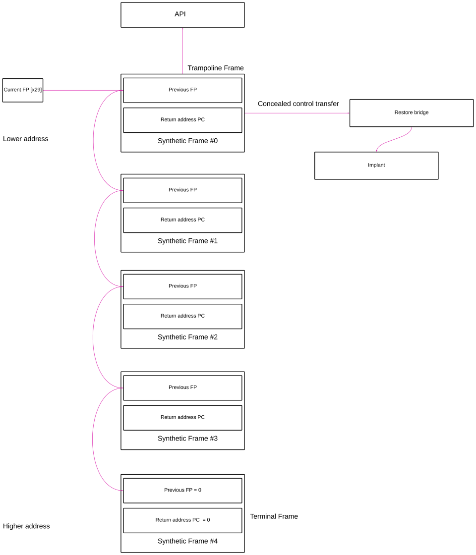
When unwinder walks through the synthetic stack, it doesnt initiate any control transfer, as long as the stack layout conforms to the ABI specification of the platfrom, stack gets succesfully unwound. But this is not the case when the api finish execution and control returns to the caller as the synthetic frames dont have a valid execution context, it will lead to inevitable crash. By placing a special frame called trampoline or gadget frame before api frame, we can take the exection back to our implant in unbacked memory. The trampoline frame connects the api frame to rest of the synthetic frames by placing its frame address in the x30.
Any branch instruction in the loaded frameworks in the process memory that takes a non volatile register as its operand can serve as trampoline frame. Keep in mind code in dylib cache are all compiled for Arm64e meaning PAC is enforced. So gadget need to be properly signed before using it. Instructions mentioned in the Arm64 branch instructions section.
The restore bridge is responsible for restoring registers x19–x30 and stack back to original state so that implant can resume execution.
How PAC affects synthetic frame unwinding and control transfer?
Common ARM64e framed function
Functions compiled for Arm64e architecture have a prologue and epilogue as shown below. Only addition to the code here is the usage of the instruction pacibsp before allocating 16 bytes on the stack to preserve frame pointer and return address. The instruction pacibsp signs the return address in x30 with value in sp as the modifier/discrimator before placing it in stack memory. Upon function exit, retab autheticates the return address. Remember the stack pointer before 16 byte allocation can be accessed relative to new frame pointer, ie 16 byte allocation by reading x29 + 0x10, which serves as the modifier/discriminator in pointer signing.
_function:
    pacibsp                          // sign x30 with key B and entry SP
    stp     x29, x30, [sp, #-16]!
    mov     x29, sp

    // function body

    ldp     x29, x30, [sp], #16     // restore signed LR and entry SP
    retab                            // authenticate with key B + SP
A summary of instructions used to sign and autheticate return address.
| PAC Instructions | Description |
|---|---|
| PACIBSP | PAC signs; I means an instruction pointer; B selects key B; SP supplies the stack-pointer discriminator. The signed result replaces LR. |
| AUTIBSP | AUT authenticates LR using instruction key B and the current SP. Success recovers its canonical address; failure traps or produces an invalid pointer, depending on the hardware sequence. |
| RETAB | Authenticates LR using the IB/SP return-address convention and returns. Conceptually, it combines AUTIBSP with RET. |
ARM64e signing of synthetic LRs
Each synthetic saved PC is signed with key B and that frame record’s modeled CFA:
modifier = syntheticFramePointer + 0x10  //stack pointer value for the frame
signedPC = PACIB(rawPC, modifier)

verify
    AUTIB(signedPC, modifier) == rawPC
Authenticated trampoline to restore bridge transfer
When working on Arm64e binaries, remember any kind of control transfer warrants pointer authetication. In our case following are the few critical paths that require pointer authentication:
- API to trampoline control transfer
- Trampoline to restore bridge
- Bridge to implant
Masking in action
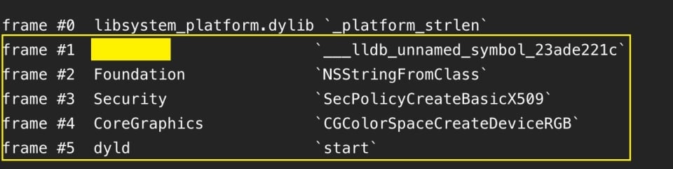
The stack trace above demonstrates execution of a masked strlen function. Our synthetic frame shows us the thread started from dyld start routine then proceeds to call CGColorSpaceCreateDeviceRGB, SecPolicyCreateBasicX509, NSStringFromClass, redacted gadget frame and finally ends up in strlen api. On windows the thread originates from RtlUserThreadStart frame followed by BaseThreadInitThunk, similarly on Mac execution starts from dyld start routine.
References
Author: Anandeshwar Unnikrishnan
