-

Adversary Simulation
Our best in class red team can deliver a holistic cyber attack simulation to provide a true evaluation of your organisation’s cyber resilience.
-

Application
SecurityLeverage the team behind the industry-leading Web Application and Mobile Hacker’s Handbook series.
-

Penetration
TestingMDSec’s penetration testing team is trusted by companies from the world’s leading technology firms to global financial institutions.
-

Response
Our certified team work with customers at all stages of the Incident Response lifecycle through our range of proactive and reactive services.
Hacking Hardware with an Arduino
Sometimes on embedded systems (such as routers or webcams), the manufacturer has left debugging ports on the board. These ports are obviously not meant for the public as they are often soldered over, and protected by the device’s outer casing. Accessing these ports can be quite prosperous for an attacker, as it might give them a shell on the system otherwise unobtainable through other means. These ports will often communicate over the serial protocol, and rage of interfaces including JTAG, SPI, and UART. Typically researchers will utilize custom hardware such as the BusPirate, JTAGulator or the Shikra to interface to the device.
Here we will be using an Arduino Uno/Nano/Mega to fuzz the debug pins on a router, and then use the Arduino as an USB to Serial converter to talk to the device and hopefully obtain a shell. Please note that this project has been created to talk over Universal Asynchronous Receiver/Transmitter (UART), other projects such as JTAGenum have been created to communicate over other interfaces with an Arduino.
Firstly, the physical debug pins need to be identified. I was fortunate enough to have breakout pins already soldered into what looked like a debug port on an old router:
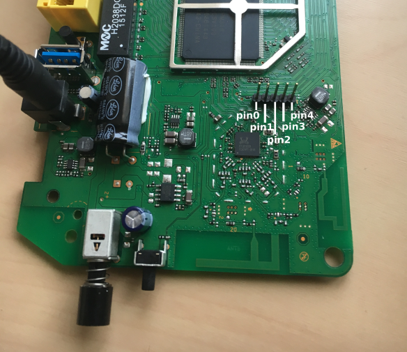
For ease of reference, we will assign the pins from left to right the names: pin0-pin4 respectively. Out of these 5 pins, We are looking for Ground, Tx (transmit), and Rx (receive), to be able to communicate with the router. Luckily, we can perform a continuity test on the pins with a multimeter to identify ground. This turns out to be pin1 (second from the left).
Next, we want to identify which pin is transmitting data (Tx) and on what baud rate, this is where the Arduino comes in. We can use the Arduino’s SoftwareSerial library to emulate a serial connection on all the unknown pins, and listen during the device boot process. Any port that transmits data is more then likely to be our Tx.
Firstly, upload the MDSec UartFuzz code project to your Arduino
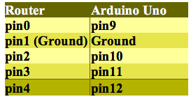
Next, attach the routers ground pin (pin1) to Arduino’s ground. Then plug the pins from the router sequentially from 0-4 (excluding ground!) into your Arduino pins 9-12 (these values correlate in the code, change and expand as needed):

Configuration:
Boot everything up, including the router. Using the Arduino IDE’s Serial monitor, we can now see the software in action. Remember we need data coming through the pins, so keep resetting the device intermittently to ensure the booting process is sending data:

The device outputs:
[code=”bash”][+] Data found on pin: 0
[?] Would you like to fuzz baud rate? y/n[/code]
Sometimes other pins jump/transmit data when powered on or off, so I have given the user the choice to fuzz a pin or carry on looking for more data. It’s probably best to say no the first time, and see which pin repeatedly transmits data. In our case, pin0. We can also see that the software fuzzed the baud rates for us, and it looks like rate of 115200 gives us clear text:
[code]—[57600]—
B��Ň��$����G�B��Ň�䀤$�Ņ��b
—[115200]—
wlan wps eoabled[/code]
Note that ‘wps eNabled’ has some corruption, this is due to the SoftwareSerial’s implementation using Bit-Banging, this is not as precise as UART – its worth bearing that in mind when looking for cleartext. Now that we know Ground, Tx, and the baud rate, we can attempt to read from the device which can hopefully help us find out Rx (Rx fuzzing yet to be implemented).
Turn your Arduino into a TTL-Serial-to-USB converter by removing the ATmega chip, or simply connecting reset and ground together (depending on your model, lookup the method). Then rewire the circuit as follows:

Configuration:
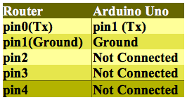
Please note that usually Tx always wires up with Rx! However this seems inverted on my Arduino Uno, try pin0 (Rx) on your Arduino if this doesn’t work for you. Spin up your favorite software to connect to a serial console (I’ll be using minicom), and set the baud rate to 115200. Reset the router, and Voila:
[code]
——————-
– VER5610 bootrom –
——————-
–
>> hit <ctrl+c> to stop autoboot:0
–
———————————-
– Flash type ………. [ SPI ]
– Boot mode ……….. [ NONSEC ]
– Read page0 ………. [ OK ]
– DDR …………….. [ OK ]
– bootloader ………. [ OK ]
———————————-
–
>> startup bootloader…[/code]
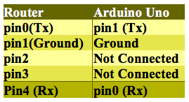
Unfortunately, at the end of the boot process we don’t seem to get a shell or a prompt, making it difficult to test for Rx. However, we do see that the beginning boot process can be interrupted. The final process is as simple as connecting one cable to the Arduino’s Rx pin (yes, this normally should be the Tx pin as this will be Transmitting data), and keep tying the remaining 3 pins on the router, and pressing ctrl+c during the boot process. If it interrupts, you know you’ve hit Rx.
The final wiring for Rx and Tx communication was as follows:
Interrupting the boot process gives user access to the #hi bootloader shell:
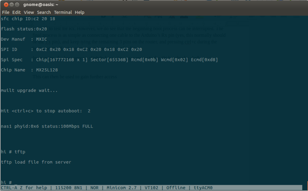
The tftp command can now be used to upload a custom kernel image to exploit the device further, as described in this MDSec post.
Happy Hacking!
This blog post and UARTFuzz were written by Alexis Vanden Eijnde.